Project overview

For this project, we had to created the 60 second which counts from 0 to 59 and resets at 60.
PLD circuit
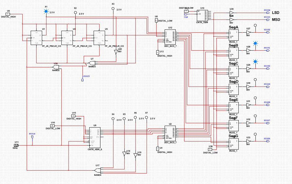
only differences between DMV display and 60 sec timer are types of counter and logic gates that I used and the range of the counter.
Conclusion
1. Synchronous counter works at the same time with one clock. On Asynchronous, first counter is only clocked by the clock and has to wait for the previous counter.
2. Difference between 163 and 193 is that 74LS163 is only counter that shows detected number.
3. First I used my previous PLD design to modify to sixty second timer. I replaced ones unit display with a 74LS163 MSI counter and tens unit display with SSI logic gates (J/K). Then, I connected the tens clock from ones output which allowed to carry the value. Then, I designed the reset switch which it would reset to 0 whenever it detects 59. To design this switch, I looked over the DMV display for the reference.
4. Most of my classmates created similar design as mine. Only difference could be the how to setup the reset switch.
