
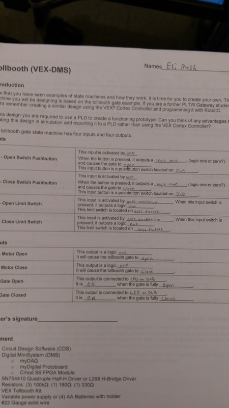
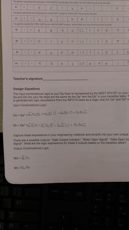
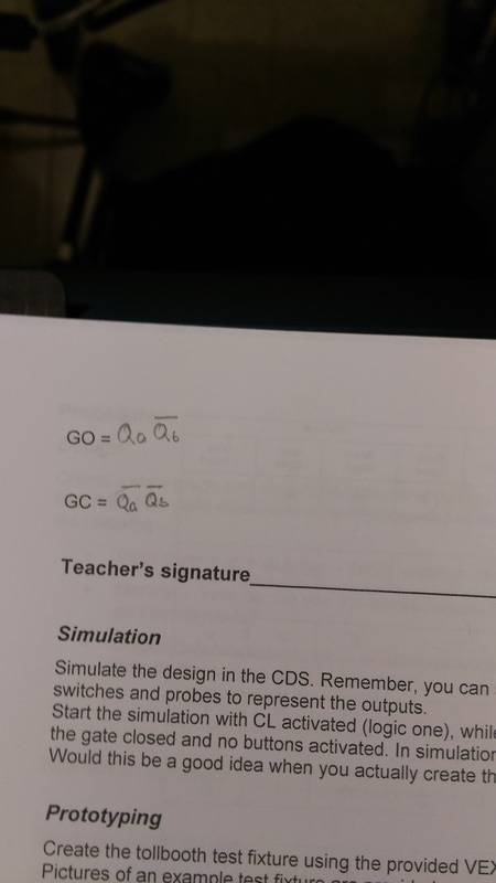
The inputs are OS, CS, OL, and CL. The Outputs are MO, MC, GO, and GC. The outputs are depend on the inputs, which determine the state of the machine. When the outputs activate by the inputs, they send the output a signal to open or close the motor or to turn on a LED.
conclusion
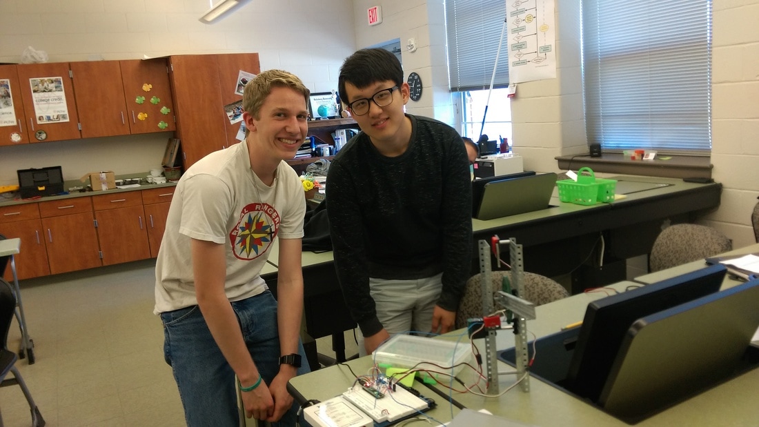
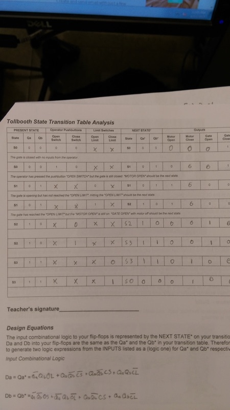
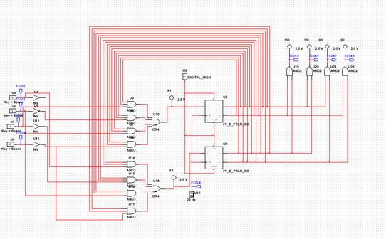
In this project, Eli and I had to build a tollbooth state machine out of VEX parts and in MultiSim. Then,We transferred the program to the board which allowed the tollbooth operate. We started this project by looking at the state graph and transition table to understand what was going on in the graph/table. I started building the tollbooth out of the VEXparts while Eli started to build the working simulation in MultiSim. For MultiSim, we needed to understand the inputs and the outputs of the flip flops which came from the six simplified logic expressions. Starting out with gate closed LED would be on, then we would switch on the open switch and the motor would open. It would then hit the open limit. After the open limit, it activated the close switch which would turn on the motor close. The close limit would then turn on and all the states would then be completed.
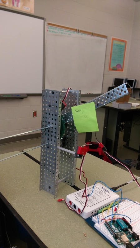
In the tollbooth project, we had to use the motor so it would turn a gear and allow the arm of the tollbooth to go up and down. The open limit was placed at the top where the arm could hit it and signal it that it was open. At the bottom there was a close limit that the arm would hit and signal that the gate was closed. Breadboard was complicated since we had to spend a lot of time in this.
What I learned about schematics in this project is it looks very complicated but if you take your time and trace all the lines you will be successful in the actual wiring.
So, be patient is the key. Another thing is that you have to be very careful connecting components to the right place and that you do not forgot any connections.
What I would do differently next time is that I really have to comprehend the circuit. Not just going straight to the project because we already have this part.
