Jaehwa$Eli
constraints
In this project, we need to demonstrate the capabilities of an engine mount and show the different materials that are used to build it. We demonstrate how stress will affect an engine mount and show how we can get the least amount of strain on the firewall by simulating frame analysis. There was certain constraints that we had to follow.
a. The large plate represents the aircraft firewall as shown in the image below. This must be grounded as the stable part of the frame. Use fixed constraints on the six firewall to structural member attachment points.
b. The structure will support one Lycoming O-300 engine (250 lb) attached at the three points indicated.
c. The structure will be loaded with negative 3 G and positive 6 G which is simulated by exaggerated engine weight due to sudden aircraft acceleration or a change in attitude.
d. The structural members will be 1 ½ in. ANSI pipe.
e. Frame members should be mitered as necessary.
gantt chart

We each decided what we wanted to do with the project. I build and design the firewall and simulated the frame analysis. Eli decided to do all the bookkeeping with research and weebly development. The weebly development would also fall in with the written report. With this we were able to divide up the work evenly and get the project done effectively and efficiently.
Procedure
To start preparing for the project, Eli conducted a research about the engine that would be by taking the link on mypltw.org to the Lycoming website. Eli was not able to find a Lycoming O-300. Though, he did examine the other engines to see what I could draw from those. Engines are pretty narrow in length as they have a more cylindrical appearance to them. The material investigations also helped out a lot as they put all the materials and gave the strengths and weaknesses of each of the different aspects of that material. With this in mind, we were able to use the investigations in inventor to work with stress testing and the pipe frames that work with the wire frames of the original project. I designed the engine mount by taking the template and first putting pipe around the different wire frames. Then I started trimming the piping to the face of the firewall so that the pipe wouldn't be sticking out and defying the laws of the physical world. At last, I used miter joints on the poles that combined at the place the engine would be attached to. This was conducted so that the pipes would be able to fit into one another when they joined at the engine mount. After constructing the frame, the next part was the stress tests, and how they affected the engine mount as a whole.
test
We completed three different types of tests. The first one was the affect of the frame at 1 G or 1 unit of gravity. This would be to show the frame at the set position when it is on the ground. The frame has a little bit of bend and it can take on the weight of the engine. With that in mind we went onto our next test of the Positive 6 G. This is supposed to represent the amount of weight that is acting on the plane when it is in flight. The pipes bent a little bit downwards which was to be expected as it had more weight on that area than when it was normally on the ground. Finally, we conducted a lift test as it had to go through Negative 3 G's of force. This made it so that the pipes bent upwards in the force of lift, which was to be expected. If both the forces of lift and weight were conducted at the same time, then we would see a pretty equal margin of the frame as it wouldn't bend as much since force is being applied in both directions. Our design meets the constraints by having the firewall be our large plate and also grounded with our pipes being pinned to the frame. We did our research on holding the Lycoming engine as well so that we could figure out how the engine would be mounted. There was also the different stress tests that would have to be conducted, as they were explained just above. The members all are 1 1/2 in ANSI piping. And we had to miter the joints and also perform trim to face to make the structure work as a whole. In final, the material that we used was steel, mild. We did this because steel is very inexpensive, and it is also the strongest in tension and compression. With that in mind and the beams having to bend a little bit with the different amount of forces being applied in the terms of lift and weight, steel was the best option. It may be heavy but the engine should be able to overcome that in total.
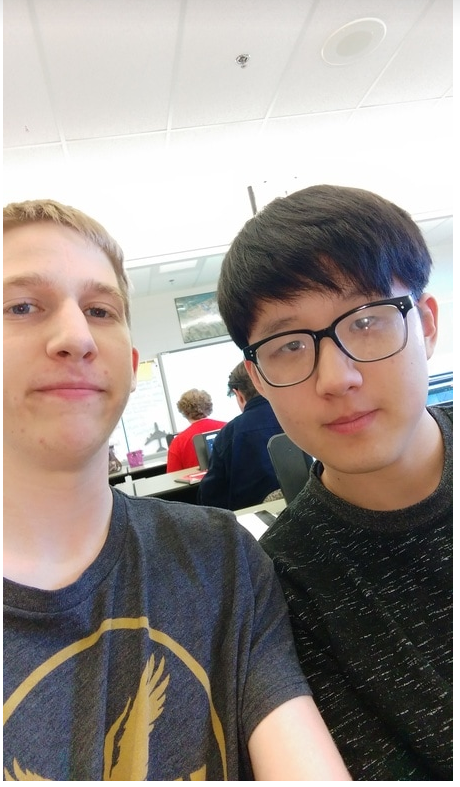
1G
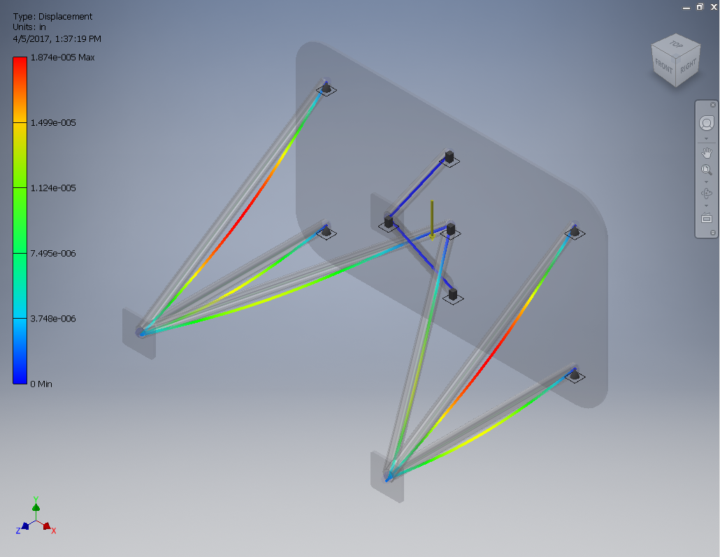
-3G
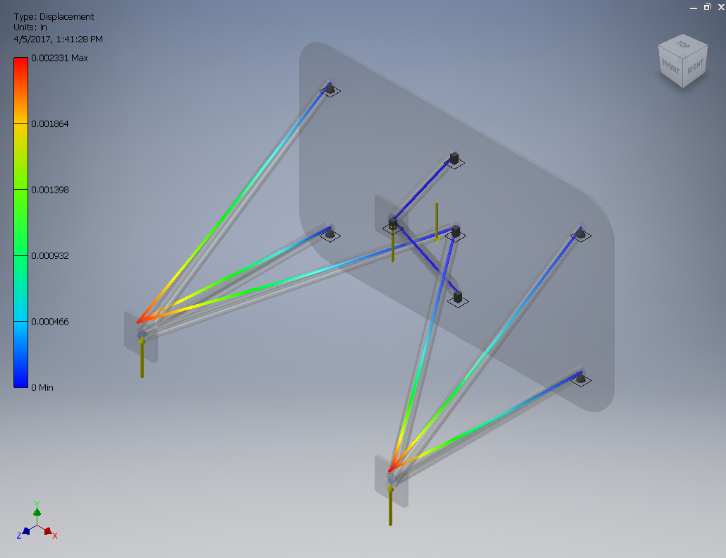
6G
conclusion
What we learned as team in is that how forces and materials can affect a plane differently. We had to try many different pinning and we conducted a good 12 test on trying to figure out what was the best pinning and fixed combination of force application. It was also good to learn more about the teamwork that Eli and I have when we can fix our minds on what we have to do. Eli contributed his research skills as well as his knowledge of structural setup for paperwork. I applied what I learned in Inventor and conducted the stress tests for the project. The frame generator is very useful in the aerospace area, as it can be used to save plenty of time. Instead of taking the part and extruding several sketches and then filet certain edges, you can take the certain sketch and make a frame around it that can be changed material wise. It helps out a lot when time is short and if you are just lazy as well.
