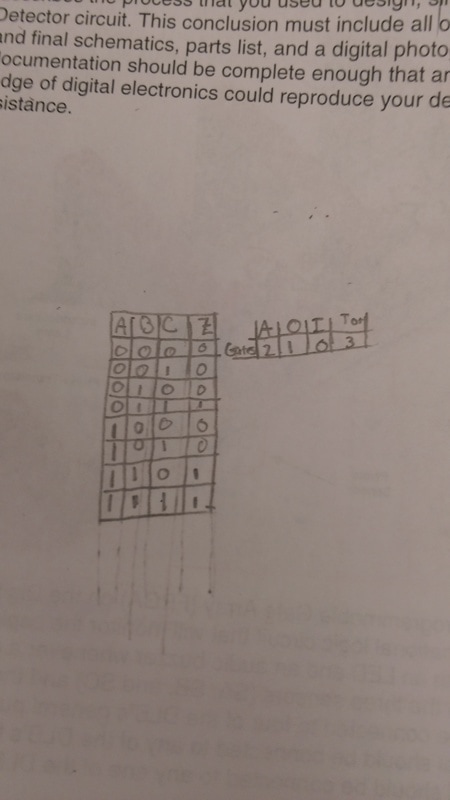
For this project, we had to design a circuit that would display a copy jam on actual copy machine. The paper jam occurs when 1st and 2nd or 2nd or 3rd sensors detects the copy jam. When these occurs, an LED indicator light will go off as soon as the jam is cleared. But, buzzer doesn't stop until we hit the reset switch.

circuits
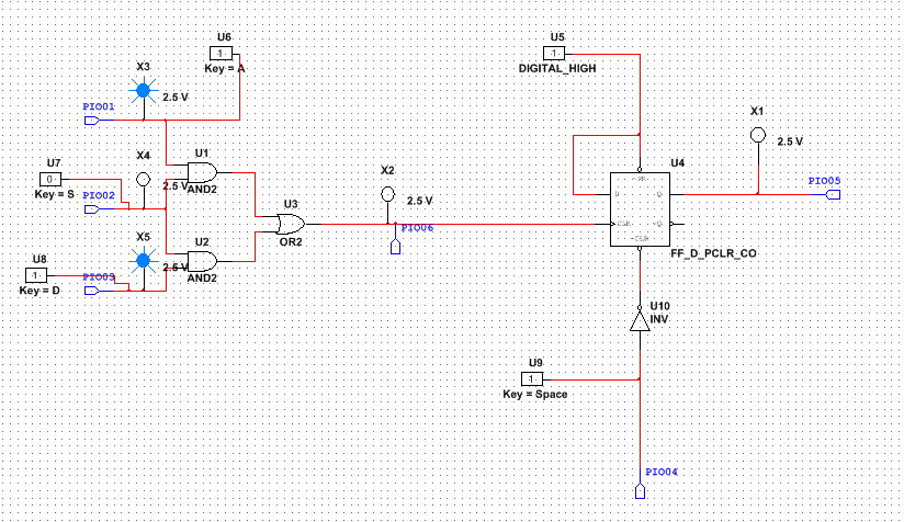
we used resistors reduce current to the lights. We use a flip flop to hold the buzzer on until clear is turned off on the flip flop. The combination logic was used to send a signal to the motor of the copier and turn it on and off depended on the existence of the jam.
The buzzer continues to sound until the reset switch is pressed. Because, it is connected the a flip flop which allows for the buzzer to remain on since there isn't a input for D and will reset when the clear is turned OFF on the flip flop.
The buzzer continues to sound until the reset switch is pressed. Because, it is connected the a flip flop which allows for the buzzer to remain on since there isn't a input for D and will reset when the clear is turned OFF on the flip flop.
conclusion
This project was more complicated than the previous project. Because, copy jam required to build extra part(copy jam tester) and wire it with that in consideration.
